MEP engineers face crowded ceiling voids every day. Pipes, ducts, cable trays, and conduits compete for the same tight space above the grid. Scan to BIM gives these engineers a clear path forward. Laser scanners capture the real condition of a building or a physical area. Modelers turn that data into accurate digital models. Teams then coordinate every trade inside one shared environment.
This workflow keeps mechanical, electrical, and plumbing systems aligned from the first day. Engineers spot conflicts on screen long before teams lift a single pipe. The result delivers cleaner installations, faster schedules, and fewer surprises on site.
Field reality drives this approach. Older buildings hide ducts behind ceilings and walls. New designs must fit around existing structure and services. Scan to BIM shows you the obstacles before you start. Engineers can plan their routes around what's actually there, not what some old hand-drawn sheet claims.
Understanding Scan to BIM for MEP Engineering
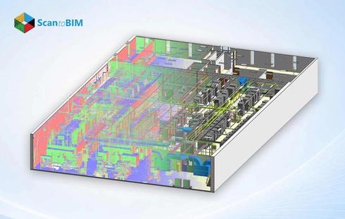
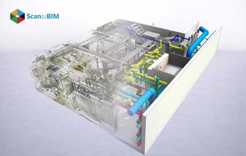
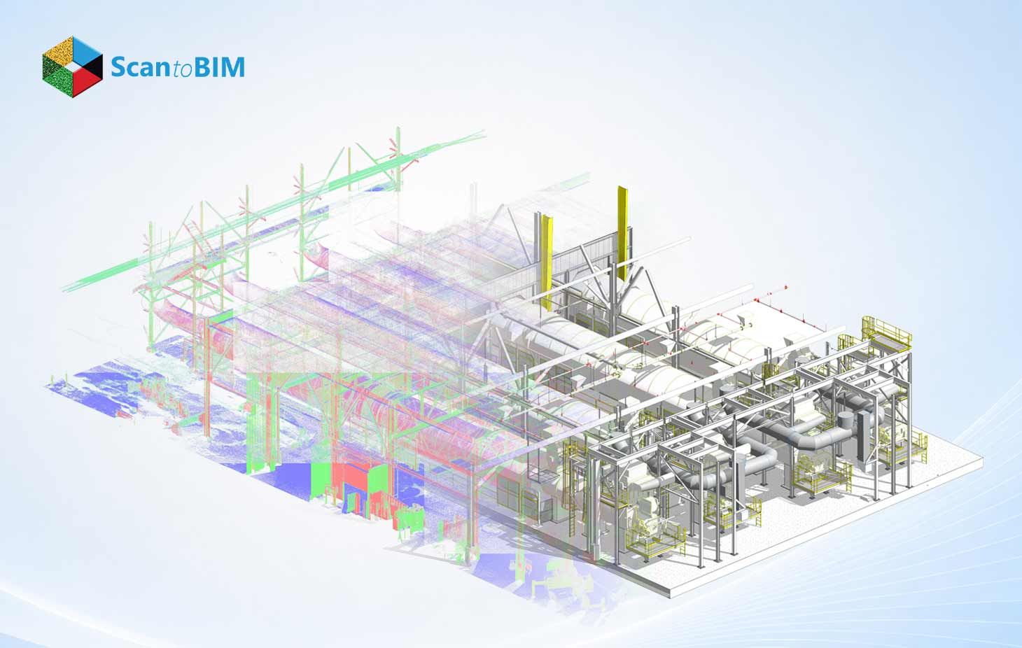
Scan to BIM converts laser scan data into intelligent 3D models. A scanner sweeps a space and records millions of measured points. Each point holds an exact position in three dimensions. Together these points form a point cloud that mirrors the physical site.
Modelers import this cloud into Revit. They trace ducts, pipes, beams, and walls directly over the scanned geometry. Each modeled element carries real dimensions and trade data. The finished model reflects the building as it truly stands today.
Scan to BIM for MEP engineers builds a single source of truth for every discipline. Mechanical teams see duct runs. Electrical teams see conduit paths. Plumbing teams see pipe networks. Everyone works from the matching coordinates.
The intelligence inside the model sets this method apart. Each duct knows its size, material, and airflow class. Each pipe knows its diameter and system type. Engineers query these properties at any moment. They run accurate quantity takeoffs from the same model. They also schedule equipment directly from embedded data.
Why Clash Detection Matters in MEP Projects
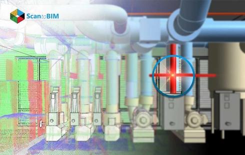
MEP systems pack heavy infrastructure into slim corridors. A 600 mm duct, a sprinkler main, and a cable tray often share the same ceiling zone. Tight spacing breeds physical conflicts between trades. Clash detection finds these conflicts inside the model.
Early detection saves serious money. A conflict caught on screen costs minutes to fix. The same conflict caught on site costs days and triggers change orders. Research confirms the financial upside here.
Clash-free MEP design protects both budget and schedule. Teams enter the field with validated routes. Experts install systems correctly the first time.
Three clash types shape every coordination effort. Hard clashes occur when two elements share the same space. A pipe through a beam shows a clear hard clash. Soft clashes occur when elements crowd required clearance zones. A valve too close to a wall blocks future access. Workflow clashes occur when trade schedules collide on site. Each type demands its resolution path.
Common Design Coordination Challenges in MEP Systems
Coordination breaks down for clear reasons. Separate teams design separate trades in separate files. Mechanical drafters route ducts. Electrical drafters route trays. Each team works toward its own goals.
A few things tend to cause the same conflicts over and over:
- Sequencing gaps: Ducts usually get routed last, so they end up fighting for whatever space is left.
- Elevation overlaps: Pipes and trays both want the same height inside a shaft.
- Penetration conflicts: Several services try to pass through one structural opening.
- Clearance shortfalls: Crowded layouts eat into the room you need for maintenance access.
Old 2D drawings tend to bury problems like these. Flat drawings show plans and sections separately. Engineers struggle to picture how trades stack in real space. Scan to BIM solves this gap with a unified 3D view.
Communication gaps widen the problem further. Trade teams don't always update their drawings on the same schedule. One team revises a route while another keeps an outdated version. These mismatches surface only during construction. A shared 3D model erases version confusion. Every discipline reads the same coordinated geometry at once.
Role of Laser Scanning in Existing Building Documentation
Existing buildings rarely match their original drawings. Decades of renovations shift walls, pipes, and ducts. Field teams need accurate records to plan new work.Laser scanning for MEP design supplies that accuracy.
A scanner captures every visible surface in a room. It records structural members, existing services, and finish locations. The scan documents the true site within millimeters. Engineers gain a faithful record of current conditions.
That kind of documentation makes retrofit work a lot less of a gamble. Scan to BIM reduces clash detection errors by grounding every new route in measured reality. Teams design around real obstacles. They avoid clashes with hidden existing infrastructure.
MEP As-Built Modeling turns these scans into permanent records. Facility managers keep these accurate models and reuse them later. Each renovation starts from verified data.
Scanning also cuts site visits for the design team. One thorough scan captures the whole space at once. Engineers measure any dimension later from the point cloud. They check ceiling heights, shaft widths, and pipe positions remotely. This single capture replaces repeated trips with a tape measure. Teams save days of fieldwork on large facilities.
How Point Cloud Data Supports Accurate BIM Modeling
A point cloud forms the backbone of every Scan to BIM project. Each scanned point anchors the model to physical truth. Modelers snap their Revit elements straight onto these points, so the model picks up real-world accuracy.
Point Cloud to BIM for MEP pays off in ways you can actually measure. Modelers verify pipe diameters against scanned geometry. They confirm duct elevations against captured surfaces. They place equipment exactly where the scan shows it. Guesswork disappears from the process.
Clean point cloud data speeds the entire workflow. Crisp scans let modelers trace geometry quickly. Registered scans connect multiple scan positions into one dataset. Engineers move from raw data to a working model with confidence. Scan to BIM reduces clash detection errors at this stage too, because every modeled element is checked against real scan data rather than assumptions.
This is also the stage where quality control keeps everything accurate. Modelers compare each element against the underlying cloud. They flag any gap between modeled geometry and scanned points. When something's off, they fix it on the spot, and that keeps the model matching the real building. Everything coordinated later depends on getting this part right.
Workflow of Scan to BIM for MEP Projects
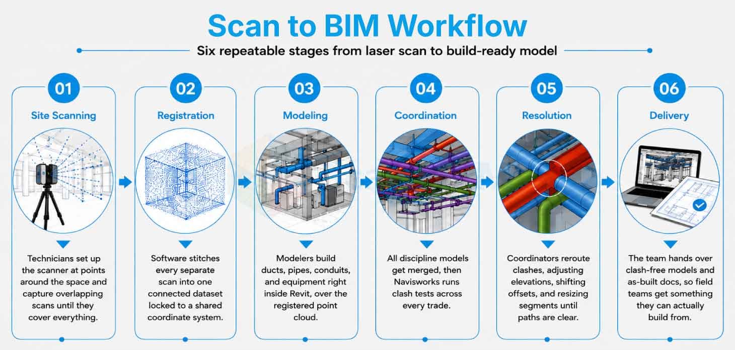
The whole thing moves through a set of clear stages you can repeat on any project, with each one passing checked work to the next.
Stage 1: Site Scanning
Technicians set up the scanner at different spots around the space and capture overlapping scans until they've covered everything, which gives them a complete point cloud.
Stage 2: Registration
Software stitches all those separate scans together into one connected dataset. Each scan locks to a shared coordinate system.
Stage 3: Modeling
Modelers build trade elements over the registered cloud. They build the ducts, pipes, conduits, and equipment right inside Revit.
Stage 4: Coordination
All the discipline models get merged, then Navisworks runs clash tests across every trade.
Stage 5: Resolution
Coordinators reroute whatever's clashing, adjusting elevations, shifting offsets, and resizing segments until the path is clear.
Stage 6: Delivery
The team hands over clash-free models and as-built documentation, so BIM professionals get something they can actually build from.
Keeping it structured like this helps the project stay on track. Each handoff carries verified data forward. Documentation follows along through every stage. Coordinators log each clash with its reference number, note which trade owns it and what fix everyone agreed on, then chase it until it's marked closed. This audit trail proves coordination quality to clients. It also guides future teams through similar conditions.
Using Revit and Navisworks for Clash-Free MEP Design
Revit authors the discipline models. Engineers build mechanical, electrical, fire safety, and plumbing systems with full parametric data. Every element carries its dimensions, materials, and connection details. Revit will also flag clashes inside linked models while you're still designing.
Navisworks runs the coordination process. It combines models from many sources into one federated view. Coordinators select two trade models and launch a clash test. The software lists every conflict with exact locations.
A typical Navisworks workflow runs through clear steps:
- Import each discipline model into the federated scene.
- Define clash rules for hard and soft conflicts.
- Run the test between selected trade pairs.
- Review each clash with grouping and filtering tools.
- Export a clash report for the coordination meeting.
Teams meet around these reports. They assign each clash to a responsible trade. They agree on routes and update the models.MEP Clash Detection closes the loop with verified resolutions. Experts then build from coordinated, conflict-free designs.
Clash matrices guide the priority of each test. A matrix maps which trades check against which trades. Structure checks against mechanical, plumbing, and electrical. Mechanical checks against plumbing and fire protection. This grid keeps coordinators focused on real risk pairs. They tackle the high-priority tests first and clear the critical conflicts early, which brings some order to what's otherwise a pretty messy coordination job.
Technology Advancements Improving MEP Coordination
Coordination tools grow stronger each year. Cloud platforms now host federated models online. Teams across regions review the same model together. That means distance stops getting in the way of working together.
Photogrammetry now supplements laser data on many projects. Cameras capture color and texture across wide areas. Engineers blend these images with point clouds to get a fuller picture. Drones reach high ceilings and rooftop plant rooms safely. This combined capture documents zones that teams struggle to access. The model gains detail across the full building envelope.
Future of Scan to BIM in MEP Engineering
Scan to BIM points toward fully connected project delivery. Digital twins will carry MEP models through the building lifecycle. Facility teams will monitor systems against live model data. Operations will draw directly from as-built accuracy.
Prefabrication will lean harder on coordinated models. Fabricators will cut duct and pipe sections from validated layouts. Modules will arrive ready to install. Field assembly will speed up across the board.
Many firms now choose outsourced MEP Scan to BIM services to scale these capabilities. These specialist teams hand over registered scans and coordinated models whenever you need them, which frees up in-house engineers to focus on the design itself. The partnership expands capacity without heavy overhead.
Standards continue to mature alongside the technology. Owners now request coordinated models as a project deliverable. Public agencies in many regions mandate BIM on large projects. These requirements push Scan to BIM into mainstream practice. Engineers who adopt the workflow early gain a clear advantage. They deliver accuracy that clients increasingly expect.
Conclusion
Scan to BIM gives MEP engineers a dependable route to clash-free design. The workflow starts with accurate laser scans of the real building. It builds detailed models that mirror site conditions. It coordinates every trade inside Revit and Navisworks. Teams resolve conflicts on screen and protect the schedule.
The value reaches every stage of construction. Engineers feel surer about their routes. Fabricators receive validated layouts. Field teams install systems cleanly the first time. Research backs these outcomes with measured savings and sharp error reductions.
Coordination matters because rework eats into budgets and drags projects out. Clash-free MEP design keeps things moving and prevents costs from creeping up, turning packed ceilings into systems that actually make sense. The approach rewards any team that values accuracy and timely delivery. Engineers gain control, owners gain certainty, and projects gain momentum from start to finish. This clarity carries every team toward confident, clash-free delivery.