Architects today work under growing demands for documentation speed, coordination accuracy, and construction-ready deliverables. Project owners expect fewer surprises. Contractors expect fewer RFIs. Construction teams want models that actually reflect what the building measures.
Manual surveys create a gap between teams' assumptions and the actual building. Tape measures miss complex geometries. Floor plans drawn from field notes carry embedded errors that surface during coordination reviews or, worse, during construction when correction costs multiply.
3D laser scanning closes that gap at the source. The technology captures physical spaces as spatially verified digital datasets. Those datasets go directly into BIM platforms, where architectural, structural, and MEP teams coordinate against measured geometry rather than estimated dimensions.
What follows covers how laser scanning works inside an architectural workflow, what it delivers across design and construction phases, and why AEC firms increasingly treat it as a standard part of their survey process on renovation, new construction, and lifecycle documentation projects.
What Is 3D Laser Scanning?
3D laser scanning is a survey technology that fires rapid laser pulses at building surfaces and measures the return time or phase difference of each pulse. That measurement converts into a three-dimensional point in space. Scanners collect millions of these points per second. The accumulated result is a point cloud, a spatially accurate digital record of every visible surface within the scanner's field of view. That includes walls, ceilings, floors, columns, MEP equipment, structural framing, and facade geometry.
Two core technologies drive modern scanners. Phase-shift instruments measure the difference between outgoing and returning wave phases and work best at shorter indoor ranges. While time-of-flight scanners calculate pulse travel time and suit longer-range facade or campus surveys. Both types produce georeferenced point cloud data that can be imported directly into BIM platforms.
Teams using 3D laser scanning services gain a millimeter-accurate snapshot of existing building conditions from a single deployment. That snapshot becomes the spatial foundation for every downstream design and coordination decision.
Understanding Reality Capture in Architecture
A ceiling height assumed at 3.2 meters that scans at 3.05 meters changes every ductwork decision in that zone. A column assumed at 600 mm diameter that scans at 680 mm shifts the structural connection detail. Those 150mm and 80mm discrepancies look small on paper and get expensive fast on site.
Architectural reality capture addresses that problem at the source by recording real building geometry before design teams make decisions. The captured data replaces field assumptions with verified spatial coordinates. Wall positions, structural positions, ceiling heights, and floor elevations all come from the actual building rather than from a drawing that may be years out of date.
Reality Capture Services convert that raw scanner output into formats architects and engineers use directly inside Revit, Navisworks, AutoCAD, and other platforms. Registered point clouds import as spatial reference layers. Design teams trace walls, columns, and structural elements over the scan rather than working from nominal drawing dimensions.
This capability supports multiple project activities at once: design validation, compliance verification, coordination clash detection, and construction documentation. Every discipline works from a common, spatially accurate baseline from day one.
How 3D Laser Scanning Improves Architectural Design Accuracy
Design accuracy starts with input data quality. Architects who work from inaccurate existing condition drawings produce designs that require revision during coordination or, worse, during construction.
Laser scanning eliminates that risk by delivering verified geometry at the outset of design. Architects receive measured data for every surface, opening, and structural element. Ceiling heights, column grids, beam depths, floor-to-floor dimensions, and facade profiles all appear in the point cloud measured, not estimated.
Existing building modeling from scan data removes the category of assumption entirely. Slab thicknesses get confirmed before floor finish specifications go out. Structural bay dimensions appear in the model before mechanical equipment layouts reach the engineer. Facade deviations show up early enough to affect curtain wall detailing rather than surprise the fabricator on delivery day.
That verification compresses the window in which design conflicts can grow. Teams address spatial problems at the design model stage, where a fix takes hours, rather than during fabrication or installation, where the same fix takes days and carries real material and schedule cost.
The Process: From Laser Scan to Architectural Model
Getting from a physical building to a production-ready Revit model takes four stages. Each stage conditions the quality of the next, so understanding where each one starts and ends helps project teams set accurate expectations for timelines and deliverables.

Stage 1: Site Preparation and Scanner Deployment
Survey teams map scanner positions across the building before a single pulse fires. Adjacent positions need overlapping coverage so the registration software has shared geometry to align them; that overlap is what turns separate scan stations into one unified dataset. Teams choose between target-based registration, where reflective targets placed around the space anchor the alignment, and targetless registration, where software matches common geometric features between adjacent scans.
Stage 2: Point Cloud Capture and Processing
Each scanner position captures the full visible environment: floor, ceiling, and all surrounding surfaces. A modern terrestrial scanner finishes one station in two to four minutes. Dense buildings may need forty or more positions. Technicians review coverage on-site, add positions where gaps appear, and move into registration once all zones are confirmed.
Stage 3: Point Cloud Modeling
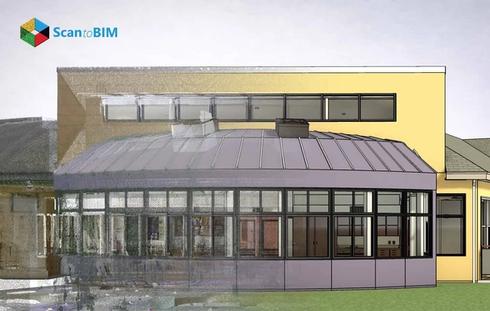
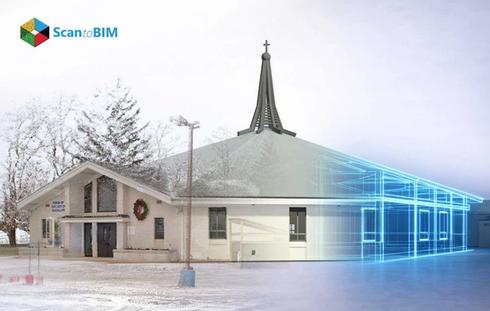
Point cloud modeling is where the scan data becomes usable project information. BIM specialists load the registered cloud into Revit and trace architectural elements directly over it including walls, floors, ceilings, roofs, columns, beams, openings, and MEP systems. Every element in the finished model references a verified scan coordinate.
Architectural Scan to BIM services deliver production-ready models at LOD 200, LOD 300, or LOD 350 depending on project requirements, with accurate geometry, correct parameters, and coordinated documentation ready for design review.
Stage 4: Quality Control and Delivery
The completed model goes through a dimensional check against the original point cloud at every critical element. Any deviation outside the agreed tolerance gets corrected before delivery. The final package includes the validated Revit model and the QC report.
Key Benefits of 3D Laser Scanning for Architects
Laser scanning delivers measurable value at multiple stages of architectural project delivery. The benefits below reflect outcomes AEC teams see across renovation, new construction, and documentation projects.
Speed of Site Documentation
A conventional survey team working a multi-story commercial building might spend two to three weeks producing measured drawings. A scanning crew captures the same building in a single day. That compression moves design development forward faster and reduces the window in which site conditions can change between survey and design completion, a practical risk on occupied renovation projects.
Millimeter-Level Spatial Accuracy
Modern terrestrial scanners achieve spatial accuracy within 1 to 3mm at standard survey ranges. That accuracy level supports detailed construction documentation, fabrication-level coordination, and dimensional verification tasks without the measurement uncertainty that manual survey methods carry.
Reduction in Site Revisits
Once a scan session completes, all measured data is available in the office. Design teams query the point cloud at any time to answer dimensional questions, verify clearances, or check structural conditions remotely, without returning to the site.
Early Conflict Detection
Architects working from scan data identify spatial conflicts between new design elements and existing building conditions during design development. That early detection prevents conflicts from reaching construction coordination or field installation stages where resolution costs rise sharply.
Better Regulatory Documentation
Laser scanning produces a timestamped, spatially verified record of existing building conditions. That record supports permit applications, code compliance submissions, insurance documentation, and asset management requirements throughout the building lifecycle.
Supporting Renovation and Retrofit Projects
Renovation projects carry a documentation risk that new construction does not. Older buildings accumulate structural modifications, MEP reroutes, and finish alterations over decades, often without updated as-built records. The drawings on file show what was originally built, not what is currently there.
Architectural laser scanning reads what is actually present in the building rather than what the drawings show. The scanner records column locations, floor elevations, beam positions, ceiling heights, and service zone conditions from the physical structure itself. Design teams work from that verified record rather than from drawings that may carry years of undocumented change.
Teams use laser scanning for renovation projects to assess existing conditions before finalizing structural connection details or MEP routing strategies. Field conflicts that stem from undocumented building changes get identified at the design stage rather than during installation.
When a ductwork contractor builds prefabricated sections from verified scan dimensions rather than nominal drawing coordinates, those sections arrive on site ready to install. Mechanical ductwork, electrical cable trays, and plumbing assemblies fabricated from scan data fit first time. That removes the field cutting and field adjustment work that typically absorbs a significant share of retrofit mechanical installation time.
Heritage and adaptive reuse projects carry additional documentation demands. Curved facades, ornate plasterwork, vaulted structural systems, and irregular masonry profiles present geometry that conventional survey methods cannot record completely. Intricate ceiling details and non-standard structural sections appear in the point cloud at the same spatial accuracy as standard rectangular building elements. Preservation architects use that data to specify repair scope and support conservation grant applications.
Integrating Laser Scan Data into BIM Workflows
Revit, Navisworks, Bentley MicroStation, and AutoCAD Structures all accept point cloud data as a native reference layer. The cloud loads as a positioned spatial dataset inside the model environment, and teams toggle its visibility on and off during point cloud modeling sessions to keep the workspace readable without losing access to the scan geometry.
Before that import step happens, the raw field data needs preparation. A Scan to BIM Company handles file format conversion, registration quality verification, noise filtering, and coordinate system alignment with the project datum. That preparation step matters more than it looks. Scanner optic artifacts, personnel movement caught in the scan zone, temporary site objects, and surface reflections all produce false points that affect modeling quality if they reach Revit unfiltered.
Point cloud to BIM services deliver models at LOD levels from LOD 200 conceptual geometry through to LOD 400 fabrication-ready assemblies. Which level fits a project depends on the project phase, the downstream use case, and what the client's BIM execution plan specifies.
As-built modeling from scan data produces a model where walls sit at scanned wall face positions rather than nominal drawing dimensions, column centerlines are based on measured point positions, and ceiling clearances reflect actual slab to finished ceiling distances. That traceability of every element back to a verified field coordinate is what gives contractors and fabricators confidence in the model before they commit to fabrication.
Architectural Deliverables from Point Cloud Data
A single scanning session supports far more than the BIM model. The same registered point cloud that produces the Revit model also feeds floor plans, reflected ceiling plans, building sections, structural documentation, and MEP coordination views. All of this is based on verified field measurements, not on interpreted drawings.
| Deliverable | Content and Use |
|---|---|
| Architectural Floor Plans | Measured wall positions, openings, column grids, and room dimensions |
| Reflected Ceiling Plans | Ceiling heights, beam exposure, soffit elevations, and light fixture positions |
| Building Sections and Elevations | Vertical dimensions, facade profiling, floor-to-floor heights, parapet elevations |
| MEP Coordination Views | Ductwork, piping, conduit runs, equipment clearances, and access zones |
| Structural Documentation | Column grids, beam profiles, slab thicknesses, and connection zone data |
| Interior Layout Plans | Exact room geometries for finish layout, furniture, and fixture placement |
Every deliverable in that list traces back to a verified field measurement. That traceability gives project teams a reliable information chain from existing condition capture through construction documentation, with no assumptions embedded at any stage.
Why Architects Are Increasingly Adopting 3D Laser Scanning
Adoption across the AEC industry has grown sharply in recent years. Project complexity, compressed delivery programs, and owner expectations for coordination accuracy have all driven that growth.
Project teams cite two outcomes most often: fewer RFIs during construction administration and cleaner coordination during design. Both trace back to the same root cause: the design team worked from measured conditions rather than estimated ones. Contractors receive cleaner models. Field crews spend more time on productive installation work.
Hospital renovation work shows this value most clearly. A ceiling plenum in healthcare carries structural framing, medical gas lines, sprinklers, HVAC supply and return, electrical conduit, and data cabling. All of these systems compete for the same 600mm of vertical clearance. Scan data confirms what fits before engineers commit to a coordination solution. That pre-verification keeps projects moving in occupied facilities where rework means clinical disruption, not just schedule inconvenience.
Government clients on educational and civic projects increasingly list as-built scan documentation as a standard project close-out requirement. That shift reflects a growing recognition that verified spatial data carries operational value beyond the construction project for future renovation planning, space management, compliance records, and facility maintenance programs.
Before committing acquisition or design fees to an adaptive reuse opportunity, commercial developers now scan candidate buildings. The point cloud answers structural condition questions, confirms ceiling clearances, and reveals MEP infrastructure status information that shapes investment decisions before high cost goes to an architect.
Heritage organizations use scan capture to document structures at risk, create conservation records, and support restoration grant applications. Scan data produces a permanent geometric record of existing conditions that survives future physical changes to the building.
Major procurement frameworks and large private clients increasingly reference reality capture methodology in BIM execution plan requirements. Practices with scan to BIM capability meet those requirements from the first submission.
Conclusion
3D laser scanning changed the quality of information available at the start of architectural design. Traditional survey methods deliver estimated conditions. Laser scanning delivers measured ones verified to millimeter-level accuracy and available as a spatial reference layer that every project discipline can work with. Architects gain access to existing conditions data that no manual method can match at the same speed or spatial resolution. Design teams work with verified geometry. Coordination teams clash to detect real building conditions. Construction teams receive models that reflect what the structure actually measures.
The scan to BIM process supports faster design development, more accurate coordination, better construction documentation, and stronger project outcomes across renovation, new construction, and lifecycle management work. As building complexity increases and project schedules compress, the value of accurate existing conditions data at the design input stage grows proportionally. 3D laser scanning gives AEC professionals a technically proven method for meeting that demand.