Pick the wrong documentation workflow on an existing building project, and the remodeling cost shows up fast. Most AEC professionals learn early: the scan equipment captures everything, and what matters is the output format you commit to before modeling begins.
Scan to CAD and Scan to BIM both start with laser scan data. The deliverables are very different. This guide walks through what separates them, where each one earns its budget, and how field practitioners decide between them on real projects.
Understanding Reality Capture and Point Cloud Data
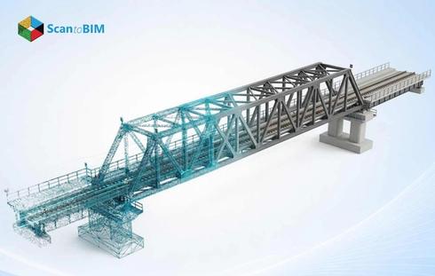
Reality capture services sit at the front of both workflows. A terrestrial laser scanner fires pulses of light across the target space. Every surface the pulse strikes returns a distance measurement, recorded as an X, Y, and Z coordinate. Modern scanners log between 500,000 and one million points each second, enough to capture a full floor plate at millimeter-level spatial fidelity across the scan station footprint.
Key software tools that process and register point cloud data include:
- Autodesk ReCap Pro: Registers, cleans, and exports point cloud data for Revit and AutoCAD workflows
- Leica Cyclone: Manages large scan datasets with advanced registration and noise filtering tools
- FARO Scene: Processes FARO scanner output into georeferenced, unified coordinate systems
Point cloud modeling happens once registration closes. Technicians comb through the unified dataset, filtering out scaffold frames, passing personnel, and airborne interference until the cloud reflects only the permanent structure. Teams that invest time in this cleaning stage get cleaner geometry on the output side and fewer correction cycles during modeling.
Scan to CAD vs Scan to BIM: Key Differences

Ask ten BIM engineers which output format their client actually needs, and half of them will say the client asked for the wrong one. The deliverable gap between these two workflows is wider than most project briefs acknowledge.
- Scan to CAD: It takes point cloud data and produces 2D drawings or 3D geometric models. DWG and DXF are the standard output formats. Every element in those files, such as wall lines, column centerlines, and duct centerlines, exists as geometry only. Fire ratings, material specs, system classifications: none of that travels with a DWG file.
- Scan to BIM: It produces a parametric model where geometry and data travel together. RVT and IFC are the output formats. A wall in Revit carries its thickness, material, fire rating, and relationship to adjacent floors. A duct carries its diameter, insulation spec, and connection logic. The model answers questions that a DWG drawing cannot.
Point cloud to BIM services teams work in Autodesk Revit, building parametric objects from the registered point cloud. Scan to CAD services teams trace geometry in AutoCAD, producing drawing sets the documentation world still runs on. What the downstream team needs to do with the output determines the right path.
Comparing Scan to CAD and Scan to BIM Across Key Factors
Same scan data, same site, same scanner two entirely different products come out the other end.
| Factor | Scan to CAD | Scan to BIM |
|---|---|---|
| Output Format | DWG / DXF | RVT / IFC |
| Data Type | Geometry only | Geometry + metadata |
| Primary Software | AutoCAD | Autodesk Revit |
| Deliverable | 2D drawings / 3D solids | Parametric BIM model |
| Clash Detection | Manual overlay | Automated, real-time |
| Lifecycle Use | Design reference | Full project lifecycle |
| Turnaround | Faster | More time required |
| Cost | Lower | Higher |
| Facility Management | Limited | Full capability |
Project leads who read this table early avoid the budget surprise of commissioning CAD deliverables when the construction team needed a coordinated Revit model all along.
Benefits of Scan to CAD
For the right project scope, Scan to CAD is the faster, leaner choice. It gets measured geometry into a usable format quickly, something renovation teams and permit applicants value over any parametric capability.
- Speed of delivery: A field scan processed through AutoCAD returns floor plans, sections, and elevations on a timeline that full BIM modeling cannot match. Teams on tight permit or feasibility schedules pick CAD for this reason.
- Accessibility: This step matters on the practical side. AutoCAD sits in the daily workflow of most AEC offices. DWG files open in tools the team already owns: no retraining, no new license, and no format conversion before drawings reach the desk.
- Cost efficiency: Cost efficiency gives CAD a clear edge on constrained budgets. Condition surveys, record documentation, and feasibility scope work rarely justify full BIM investment. Point cloud to CAD services handle these scopes at a fraction of the modeling cost.
- Drawing set compliance: It helps to decide the format on many regulatory jobs. Permit authorities, planning departments, and insurance underwriters still work from plotted drawing sets. Where a 2D deliverable meets the submission standard, Scan to CAD handles it completely.
Heritage and conservation projects fall into this category. Preservation authorities accept, and often request, 2D measured drawings. CAD output meets that submission requirement without a full parametric model.
Benefits of Scan to BIM
What Scan to BIM delivers goes beyond what any drawing set captures. The intelligence embedded in each model element justifies the investment, particularly on projects with long operational lives.
- Clash detection: where BIM pays for itself fastest. Revit Modeling Services teams load the as-built model into Navisworks, run automated clash tests across structural, architectural, and MEP systems, and surface conflicts weeks before the first subcontractor mobilizes. Catching a duct collision in Navisworks costs almost nothing. Finding it in the field costs days.
- As-built BIM Models: Give facility teams something a drawing set cannot: a queryable record of the structure. Maintenance schedules, equipment warranties, and material specs are all accessible by selecting an element in the model.
- Lifecycle intelligence: What drawings cannot replicate. The point cloud to BIM modeling process ties raw scan geometry to parametric Revit objects. Every wall, pipe, duct, and column becomes something the model reports on demand, in terms of quantities, areas, and system affiliations.
- Digital Twin Modeling: Extends the value into operations. The as-built model seeds a real-time digital twin, where live sensor data feeds back through the model interface. Facility teams track energy draw, occupancy patterns, and maintenance status without site visits.
Research found that 61% of project teams reported BIM processes reduced project errors, with 82% of BIM users confirming a positive return on investment. The same model serves architects, MEP engineers, and construction managers simultaneously, and that shared use is where the return compounds.
When Should You Choose CAD or BIM?
Project context, budget, and the downstream team's actual working environment all factor into this call.
Choose Scan to CAD when:
Permit submissions, planning authority packages, and insurance record sets all call for plotted 2D drawings, and CAD delivers those without the overhead of full parametric modeling. If the firm runs entirely on AutoCAD and has no Revit licenses in the building, there is no practical case for a BIM deliverable. Speed matters too: condition surveys and feasibility studies on tight timelines go to CAD first. Industrial plant documentation, utility corridor surveys, and one-trade recording tasks sit firmly in CAD territory. The geometry is what the client needs, and that is all CAD produces.
Choose Scan to BIM when:
Renovation work on an existing-conditions structure is the clearest trigger. When a design team needs to work around what is already there, such as structural frames, MEP runs, and concrete cores. They need a coordinated Revit model, not a stack of DWG files. Multidiscipline projects where architects, structural engineers, and MEP consultants work in parallel need a shared model environment; CAD drawings cannot support that kind of live coordination. Owners who plan to hand the building data to a facilities team after construction wraps need the model to carry that information from day one. Clash detection, preconstruction coordination, lifecycle energy analysis, and digital twin seeding all point in one direction.
The Scan to BIM workflow maps the full sequence from scan capture to model delivery, with phased guidance matched to specific project conditions.
Hospitals, airports, university campuses, and historic buildings consistently justify the BIM investment. Long operational lives and frequent renovation cycles mean the model data earns its keep well past practical completion.
Common Challenges and Considerations
Field realities create friction in both workflows. Knowing where those friction points appear helps teams plan around them.
- Point cloud volume: A floor plate scan produces point clouds from 50 to 500 gigabytes. Hardware costs are real, and file organization matters as much as processing power. Worksets and cluster segmentation keep the data manageable.
- Noise and occlusion: It appears in every scan campaign. Furniture, temporary site equipment, and personnel create artifact points. Careful scan scheduling and overlapping station positions catch the gaps occlusion leaves behind.
- Level of Detail Requirements: Vague scope can lead to unexpected issues in BIM projects. LOD 100 through LOD 500 each carry different time and cost implications. Teams that skip defining the LOD target at kickoff end up modeling far beyond what the project needs. A BIM Execution Plan written before modeling begins keeps the scope honest.
- Registration accuracy flows through to every output. Scans registered above the project threshold produce geometry that drifts from actual site conditions, and that drift surfaces during construction as costly discrepancies. USIBD-level accuracy standards give teams a shared language for specifying what the scan data must achieve.
- CAD workflow limitations: Surface when coordination gets complicated. DWG files require manual overlay to compare disciplines, a process that introduces human error. Multidiscipline MEP projects get cleaner coordination through the automated clash detection a BIM environment provides.
- Software interoperability: It determines how far the deliverable travels. IFC export from Revit opens the model to OpenBIM platforms. DWG from AutoCAD moves between most AEC environments easily. Confirming what the receiving team opens files in before the output format locks prevents handover problems that went unbudgeted on both sides.
Best Practices for Selecting the Right Workflow
Scan to BIM Services professionals run through a structured set of questions before writing the modeling scope.
- Define the project deliverable first: A permit drawing set points to CAD. A coordinated design model for a multistory renovation points to BIM. Working backward from the final deliverable removes the ambiguity that causes scope changes once modeling is underway.
- Assess downstream use: Ask the full project team what they plan to do with the output. A facilities team planning 20-year asset management needs a queryable BIM model. A surveyor producing a single drawing set needs a clean CAD file.
- Match LOD to project phase: Early feasibility tolerates LOD 200. Construction coordination runs on LOD 350. Facility handover targets LOD 400 or LOD 500. Locking the LOD at kickoff controls both scope and cost.
- Confirm scan accuracy requirements: USIBD classifies scan accuracy from LOA 10 to LOA 50. Tighter accuracy means closer scanner placement and heavier registration work. Match the LOA specification to the geometry tolerances the project demands.
- Evaluate budget and schedule together: Scan to CAD costs less and moves faster. Scan to BIM takes longer and costs more. Projects under pressure sometimes phase the work. A CAD output is produced now, and a BIM model is commissioned at the next project stage when funding catches up.
3D scanning adoption keeps accelerating: the market surpasses $16 billion by 2030, running at 4.5% CAGR from 2024 onward. Renovation, infrastructure, and heritage projects are driving much of that growth.
Conclusion
Scan to CAD documents' geometry. Scan to BIM documents a building. That distinction drives every decision about format, software, cost, and timeline. Both workflows draw from the same point cloud. The split occurs based on what the output must do once it leaves the modeling environment. AEC professionals who understand both paths stop debating tools and start matching deliverables to project needs. Accuracy, coordination quality, construction efficiency, and operational cost across the full lifecycle all follow from that one early decision. Competency in both workflows keeps teams capable across the widest range of project types.